Showing posts with label drawings / plans. Show all posts

Thursday, April 12, 2007

Drawings outsourced to China

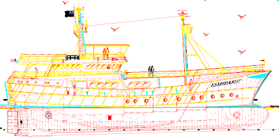
Our ship was built in 1989, before the time every shipyard used software to create technical drawing. Luckily the design of our vessel hasn't changed over the years to our ship's designer, Herman Jansen BV in the Netherland had AutoCAD drawing of newer ships that used the same hull.

However, the inside of the vessel like engine room, piping diagrams, and lots and lots of details were not available in AutoCAD. So, we just contracted a Chinese company to convert the most important of these drawings into AutoCAD to help us with the conversion and be able to provide precise and updated plans to meet future regulatory compliance.

Where would we be without the Internet ? Thanks Al Gore ! :-)

Tuesday, March 13, 2007

Latest drawings

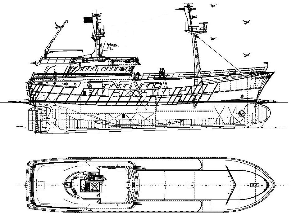
forward mast with hoist and observation platformAn update of the drawings. The new crane - should I say beam with hoist? - is now further developed. No more (expensive) hydraulic crane. It also matches the general look a lot better.

We also put a little observation platform in front of the mast, taking advantage of the support struts placed in front of it. It accommodates about 7 people. Great for whale watching.

The tenders are place on the aft deck and the access to this deck has been moved. They stick out a little bit but that's OK. We probably need a small hydraulic crane for the tenders but we're still looking at option here.

We also did a litte work on the hold below the staterooms. We put the SCUBA air compressors here and an emergency gen. set but I want to move the air compressors to the engine room and the gen. set to the anchor winch room.

This is a PDF file with a side view. This file has top views.

Slowly but surely it's coming together.

Friday, March 2, 2007

Latest drawings

wheelhouse and bridgedeck as of March 1 We are really getting in the final design stage now. The remaining areas are the top deck (fly bridge and aft. top deck deck).
This is where we'll store the tenders during longer voyages (on short trips, we may just tow them behind us).
It can also serve as the helipad or may store a float plane (in which case of course at least one tender has to be kept on the front top deck.

Here's a link to two PDF files with top views and side views. These are 800 KB files so you may want to 'right-click' them and use 'save target'.

Let us hear your comments at thorwald@ilisa.com.

Sunday, February 11, 2007

New drawings

main deckWe're slowly but surely turning our ideas into drawings.

Here the latest drawings (Feb. 20). We still need to work on the bridge, upper deck and galley but we're top dekmaking progress. Regarding the galley, we need to figure out how much cold space we need; should we create smaller cold storage chambers at the galley level or bigger ones below?

The idea is that each stateroom can has queen, convertable in 2 twins. Moreover, the 4 staterooms in the center will have a provision to put in a pullman berth, allowing a queen + twin or 3 twins. The forward 2 staterooms already have a queen berth above with twin below.
Finally, the starboard stateroom forward of the engineroom can have its 3-seater be replaced by a one twin or two twins (bunkbed configuration). Ideal for a family with 2 kids.

The crew cabins in the back on starbord now have private heads, the guest cabins are basically in there final version.

We're also planning 2 berths in the most forward section, in front of the crew cabins. This is actully the anchor winch area but it has space for 2 berths on the starboard side. It won't be big bug but it's going to be bigger than many yachts crew cabins. Also an exceptable place for kids we want to have their 'own' little space.
guest stateroomsAs to the Seamagine sub you may have seen on other drawings, it fits nicely on the main deck but for the time being, we won't carry it. This area will be the dive deck. The 'roof' of it, the section that would connect the top deck in front of the bridge and the forward deck would be removable. For the time being, it will be part of a great , huge sun deck that streches all the way from the bridge forward. A nice place to party under the bright stars and still have space for tables and a live band and what else.

For a bigger PDF version the plans, select here: side view - top view

Friday, December 1, 2006

First draft of plans by designer


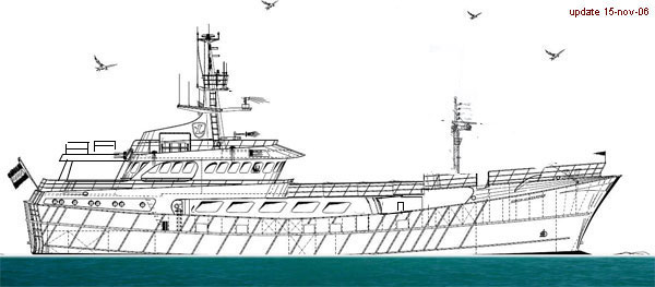
Just got this in from the designer at Herman Jansen in The Netherlands who's turning my sketches into a real drawing. I can't wait to see more.

It shows a front mast we're going to change. Not sure yet what the future one will look like but definitely something smaller. Not that it looks bad, just expensive :-).

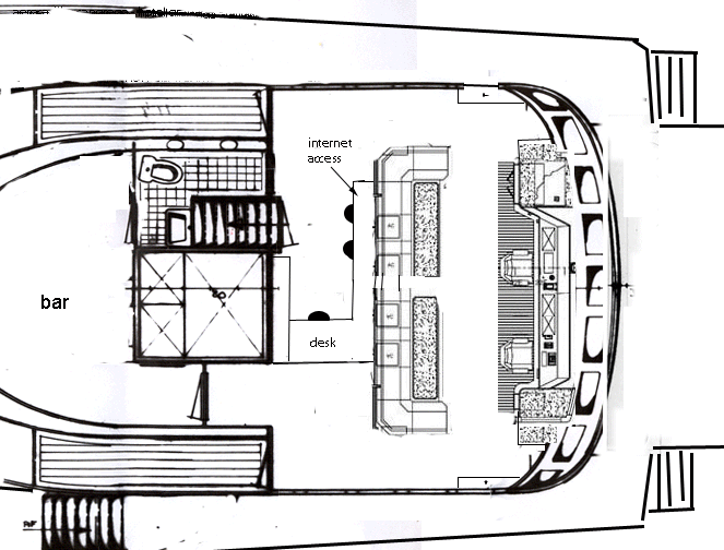
The bridge


Our first draft of the new bridge.
Ample space to walk around during operation in port, a nice settee for about 8 guests and room for all the gear.
We also create a little work area, mini-office if you want.

Wednesday, November 29, 2006

Crew cuarters


We're not quite sure how much professional crew - if ever - we need. Basically, we plan to have this vessel manageable by 2 or 3 people. I mean, it's a little bit bigger but hey, the safety is in the size !!


But not everybody operates a vessel this size like that so, to ensure the maximum resale value, we're going to create more crew space. And being a former merchant mariner myself, we're not going to put them into a close like most multi-million $$ megayachts do. Of course, these staterooms make also great cuarters for kids.

We plan 3 staterooms, each with 2 berths forward (one small queen size), under the current 'buiskap' (see picture at the bottom of this page).

One with have a private bathroom; the other will share one. There also will be a crew mess and small crew galley. The 'camera room' is for the diving folks to put their gear when they come out of the water. In this area, we also provide access to the storage below the main staterooms (the 'onder ruim').

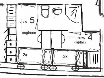
In the rear of the vessel, we'll create a small stateroom for the captain and engineer. They will share a bathroom. This way, they'll be very close to both bridge and engineroom. Of course, they will be able to monitor their relevant systems from their stateroom.


-


-


-


Storage below staterooms


This is an area which we still have to work out. Right now, there's no decent standing space (only about 5 ft/150 cm). But there would be standing space (partly), if we remove some ballast from below.
It would be a great space to but the laundry equipment and provide extra storage, especially if we create shaft to access the deck.
We'll figure out something, together with our friends at Herman Jansen, the original designers in The Netherlands.

Guest Cabins


The biggest modification of all will take place in what are now the fish and net holds.

In the net hold (the area forward of the engineroom) and fish hold, forward of the net hold, we plan to build 6 staterooms as shown.

We are considering to allow the installation of a Pullman-berth in the forward 4 staterooms (picture left) so these rooms allow up to 3 guests or 2 guests in separate berths.


Access will be from the main decks living room.
Below these staterooms there's still standing room (well, almost) and space for supplies and equipment like laundry and maybe some spare berths for crew. Or kids. Access will be from the main deck through the area indicated as 'naar onderruim'.

Forward of the fishhold is the forward engineroom. It has a gen set that was used during its days as a fishing trawler in port but now it will make space for 2 more staterooms so we'll have a total of 8 in this area. Enough for 8 couples with their friends and kids. All staterooms will have queen sized beds and some will have a 3rd berth pullman-style.

All walls, doors and floors will meet SOLAS convention passengership standards and regulations related to fire safety and noise cancelling.


Saturday, November 25, 2006

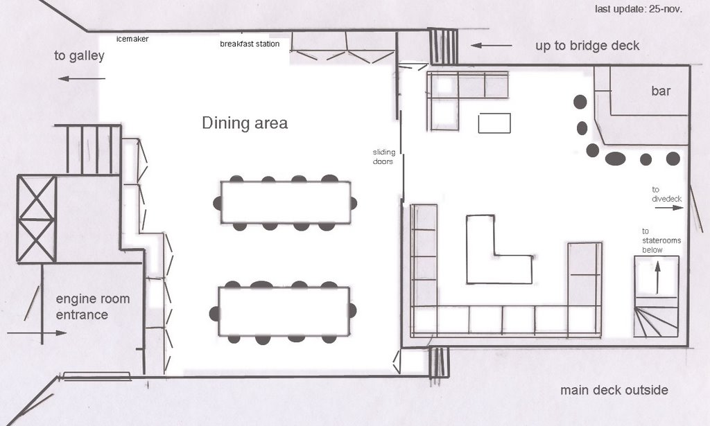
Dining & living area

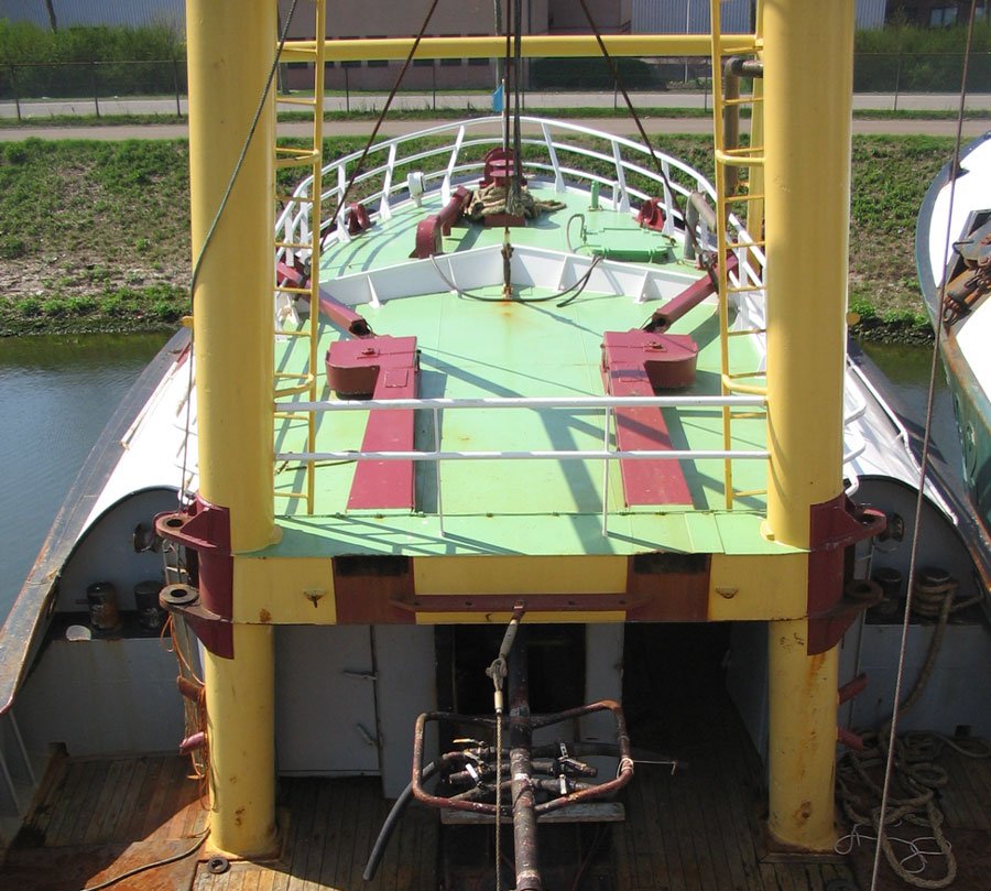
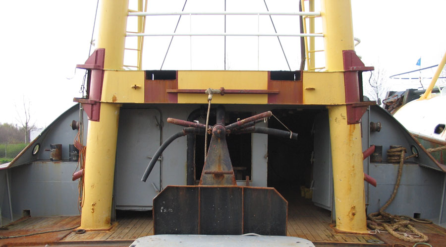
The winch room, shown on the right (and below from the outside) is located below the bridge. We will remove the winches (anybody needs 20 tons of scrap??) will be extended forward.
In here, we will create a dining area and living + bar. Of course, we can also have breakfast on the aft deck which will be partially covered. And what about the roof of the bridge? We'll add some cover there too. And possibly a jacuzzi....


The current winch room will be widened (to allow the bridge walk-around.


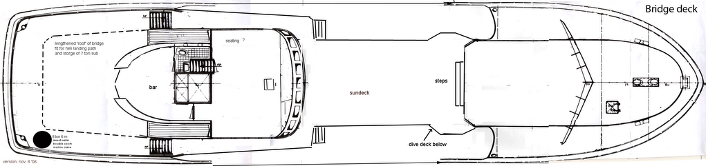
Bridge deck

The bridge deck will be modified to include a walk-around the bridge. The steps currently leading to the aft deck will be move forward just in front of the bridge.
A huge sun deck above the extended winch room (containing dining and living area) will be created forward of the bridge. We plan to add seating to the bridge, a bar in what is now the captain's stateroom and a covered terrace on aft deck on top of which we plan to store the tenders.

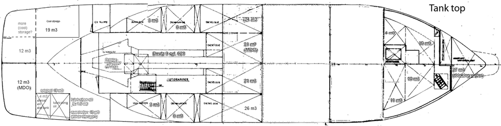
Lower (tank) deck


This drawing mainly shows the tank location. The engine room is located just after mid ships. The fish hold before the main fuel tanks.

We can currently take about 130+ tons in fuel oil (over 34.000 gallons). Filling it up is well beyond my VISA card limit!
We plan to bring this down to about 90 tons, which would still give us an economy range of about 10.000 miles, enought to make it back to Cook's bay (Tahiti) and back again without refueling.
The fuel tanks in the back will be partly converted to storage space and put in use as fuel oil day tank and and lubrication oil storage.

Main deck


The main deck. Going from bow to stern, here we'll have crew quarters and/or staterooms for kids, our dive deck, a living and dining area, the galley and more crew quarters + a room for maintainance on fine gear. Above you can see some more up-to-date drawings and I soon hope to receive the work of the designers at Herman Jansen BV

We also want to create some kind of stern platform, 'foldable' and detachable from the stern. This would be with future sub marine operations in mind. More about that in the 'sub' section. But meanwhile, it will be a great swim platform and a place to tie up our kayaks!


Side view of the vessel

Built in 1987, there are no AutoCAD drawings avaible for this vessel. As I write this, the original designer, Herman Jansen BV in The Netherlands, is converting the original paper drawings into electronic versions.

I've scanned deck plans and make crude drawings myself to explain to the designer what I want so he can put my ideas into AutoCAD or similar software. The current design draft aft is 5.1 meters (16.4 ft). This will be reduced to about 4.5 meters (2 ft. less) so we can have port holes in the side of the ship high enough above the waterline as required by the classification rules.
As you can see, lots of space.